< Return to Writings
Dynamically matching LED brightness to ambient light using a microcontroller
Work in progress, remains to be improved
This problem was the cause of many headaches whilst building my GPS clock. After changing the display to an ST7920-driven 128*64 LCD, I wanted to have the display's brightness automatically adjusted to match
ambient light, so that the display is visible across all light levels but will not be annoyingly bright in the dark. In addition, I wanted the brightness transitions to be smooth and visually pleasing.
This was an early challenge in my electronics journey, and it was a major obstacle which took a long time to crack. I am now documenting this after the fact.
Ambient light is sensed using a voltage divider containing a photoresistor, with the photoresistor's voltage measured using one of the Arduino's ADC pins. The Atmega328 on the Arduino Uno has an ADC resolution
of 10 bits, giving 1024 measurable voltage steps (2^10 = 1024), from 0 to 1023, where reading 0 volts gives a value of 0 and the reading the voltage used as reference gives 1023. The internal analog reference of
5 volts is used here.
My initial approach was to read the photoresistor's voltage, divide it by 4 (to convert to an 8 bit value, range 0-255, to pass to the analogWrite() function), and set the display backlight's PWM duty
cycle to this value. This sort of worked, but looked terrible. In constant darkness, the backlight flickered unpleasantly and jumped between brightness steps. I left the project in this state,
and had the clock's backlight turn off automatically during my hours of sleep. For the following months, this problem was bottom priority due to other things I had going on and later from disinterest.
Perhaps 8 months later, I regained interest in the problem again and found this article by codeinsecurity,
a highly valuable page that led me to the solution.
The essence of the original problem is:
- At low PWM duty cycles, changes in brightness are much more noticeable.
- When using low PWM resolution, there are large brightness steps in the bottom half of the duty cycle range
- The ADC used for sensing light level is imperfect and readings differ a little under constant conditions. Dividing by 4 made the output even more coarse.
In low light, a small change in PWM output causes a non-subtle change in brightness to be seen
The solution is to increase PWM resolution (to minimise the perceived brightness steps at low duty cycles) and apply gamma correction to the PWM output (to account for the non-linear response of human eyes).
Increasing PWM resolution is the easier part. The Atmega328 microcontroller is capable of 16 bit PWM (giving 2^16 or 65536 possible output levels). I found this article
to be useful for this. I used 10 bit PWM, to match the resolution of the ADC (using higher PWM resolution wouldn't provide any benefit).
The slightly more challenging part is gamma-correcting the output. With a low PWM resolution, this can be done with a look-up table, but increasing resolution makes the table more memory-expensive, and is
out of the question with 10 bit PWM on the Atmega328.
The graph below shows the relationship between brightness and duty cycle for a non-gamma corrected output:
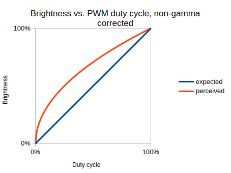
As seen on the left, in the bottom half of the duty cycle range, linearly increasing duty cycle causes a rapid increase in brightness compared to a similar change in the top half of the range. For a smooth
linear transition to be seen, the output has to be mapped to a curve below the desired straight line:
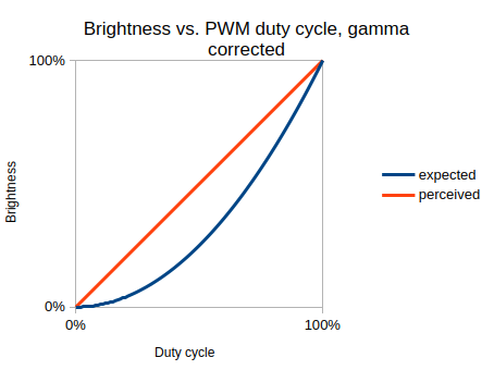
I chose to gamma correct the output in real time. One way of gamma correcting is to use an exponential function, where the output is raised to a power (the gamma value):
y = x ^ gamma
Suppose you need to gamma correct an output of 450, and a PWM resolution of 10 bits is used (giving a max value of 1023). In order to apply an exponential
gamma correction function, a value between 0 and 1 is needed, so divide 450 by 1023.
450 / 1023 = 0.44
If using a gamma value of 2, this value can be squared. Otherwise, use the pow() function. Using an integer gamma value is least computationally expensive though.
0.44^2 = 0.19
The value now needs to be mapped to the original range of 0-1023:
0.19 * 1023
This operation can be performed using integer maths as follows (still using a gamma of 2):
duty = 450 // this variable is to be set by the ADC-reading code
gammaCorrectedDuty = duty * duty;
gammaCorrectedDuty /= 1023;
analogWrite16(outputPin, gammaCorrectedDuty);
Now doing a linear sweep from 0 to 100 %, gamma-correcting each value, will create a pleasant brightness transition.
Last modified: 17MAY2025