< Return to Projects
C64 IRQ LED, a new approach
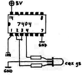
A project I have seen and considered building is an interrupt indicator for the Commodore 64, which changes the power LED's colour when the CPU receives an interrupt. The existing
solution is to use a SN74LS04 hex inverter chip, which is used to invert the IRQ signal and drive one LED, and the output of the inverted IRQ signal is inverted again and used to
drive another LED. A bicolour LED is mounted in place of the original power LED. When the IRQ pin is inactive, one colour indicates power, and when active, the colour that
indicates power is disabled and the other colour shines. The design is as pictured:
I dislike this design for a few reasons:
- The functionality cannot be disabled easily (it may be desirable to toggle the IRQ indicator functionality)
- TTL signals are being used to supply a voltage to the anodes of the LEDs
- One logic output is being simultaneously used as a logic input and as power for an LED
Some explanation of the above reasons
TTL "high" outputs can source a maximum current of 0.4 mA max, and powering an LED as pictured above by driving the anode with a signal will draw excessive output current, unless
a large series resistor is used (an high enough resistance for a low enough current would make the LED dim).
If LEDs are to be driven by TTL logic, the ideal setup is connecting the anode to 5V and driving the cathode with the logic output, as a TTL "low" output can sink 16 mA.
This, however, causes inverted LED behaviour (the LED is lit when the signal is low) and a common-anode bicolour LED will be needed, which is inconvenient.
Another problem with the above design is that a signal is used to both drive another logic input and to drive an LED. A signal driving an LED cannot also be expected to
be a valid logic input due to the high current drawn by the LED.
This new solution will use a 74HCT logic chip, whose outputs can supply 20 mA (as long as they are not used to drive other inputs).
Devising a new solution
By choosing to implement the enable/disable switch using a logic signal "EN", the following truth table can be made:
| nIRQ | nEN | Interrupt LED | Power LED |
| 0 | 0 | 1 | 0 |
| 0 | 1 | 0 | 1 |
| 1 | 1 | 0 | 1 |
| 1 | 0 | 0 | 1 |
The n prefix in nIRQ and nEN indicates that they are active low. I first completed this truth table using an active high ENable signal, and then tried with an active low ENable, as it
is here, and found that this gives a simpler result.
Looking at the column for the Interrupt LED's state, it can be represented by a single NOR gate with nIRQ and nEN at the inputs:
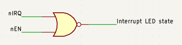
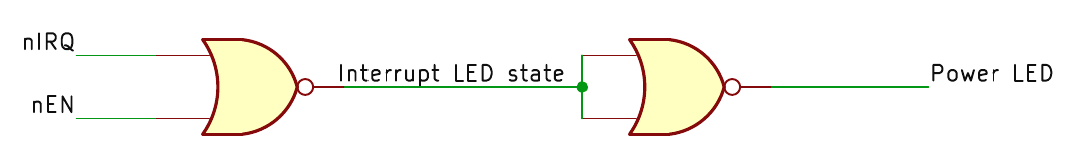
The state of the Power LED is always opposite that of the Interrupt LED, the output of the first gate can be inverted for the. The NOR gate is one of the "universal gates" as NOR gates
alone can be used to implement all other logic gates. A logic inverter can be made by tying the inputs of a NOR gate together:
The Interrupt LED needs to represent the output of the first gate, but cannot be directly driven by the same signal. The output signal can be driven through two inverters:
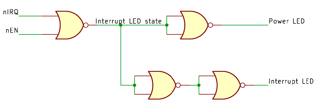
The double inverter combination results an a signal identical to the output of the first NOR gate, but it can be used exclusively for driving an LED's anode.
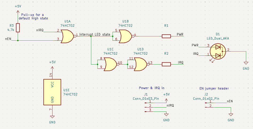
Quite conveniently, the SN74HCT02 logic chip has 4 NOR gates, so the solution can be achieved with a single chip.
The project schematic is as follows:
Created: 09JUN2025
Last modified: 27JUN2025